
During the last years, UV LED market is significantly growing thanks to power and efficiency, to increasing wave lengths absorbed by ink, varnish, glues photo-initiators.
UV LED technology is the solution of the future for the UV curing processes for applications as UV drying of glues and coating (i.e. on wood, metal, resins, electronics …), inks in graphics industry (digital printing, flexo, serigraphic) or special treatment as glass printing or automotive industry.
Applications of UV LED technology
The main applications UV LED technology are:
General characteristics of UV curing system using UV LED technology
The main parts of a UV curing system using UV LED technology are:
Optionally the following items can be included:
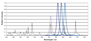
The UV LED lamps have a very selective emission peak, centered on precise wavelengths (365, 385, 395, 405 nm), in fact there are emission in UV-B and UV-C range (see figure below )
LED (single) chip size can be a fraction of mm^2 to several mm^2 (thickness<100 micron), this implies LED module scalability e flexibility in terms of shape and size.
Single LED chip are mounted on PCB using a complex wire bonding process; in addition in case of N LED module, 2N wire bonds are needed on PCB, as consequence, generated heat is really high. For this reason it is important to use an efficient chilling technique. Unlike to UV lamp ignition phase, LED module switches on instantly when low voltage /current is applied. Generally a LED chip works in voltage/current range 2-4 V 20-200mA, its UV irradiance is directly proportional to the amount of current passing through the device. If this amount of current is too high LED chip can be seriously damaged; to balance the current flow through LED chip (and so the light emission), constant-current drivers and PWM technology are used. The use of constant current driver enables individual LED chips to be traversed by continuous (non-fluctuating) currents (when powered). For application requiring different power levels, PWM techniques is used to generate different output power levels (varying duty cycle %). PWM techniques is based on instant answer of LED diode, switching really quickly from ON state to OFF state. Max irradiance (peak value) is always the same for all power level, the ON interval is changed according to needed power level. For each LED module, there is DRIVER BOARD that:
The driver board can be integrated to LED module or to PSU. Generally LED module integration is better because diode electrical noise is minimized and interconnect cables sized is reduced.
The key factors to consider in choosing or designing UV LED system are:
Note: LED output is monochrome and UV light intensity depends on wavelength (for instance: λ=365nm I=2W/cm2 – λ=395nm I=10-16W/cm2)
Advantages of UV LED technology, comparing with UV lamps
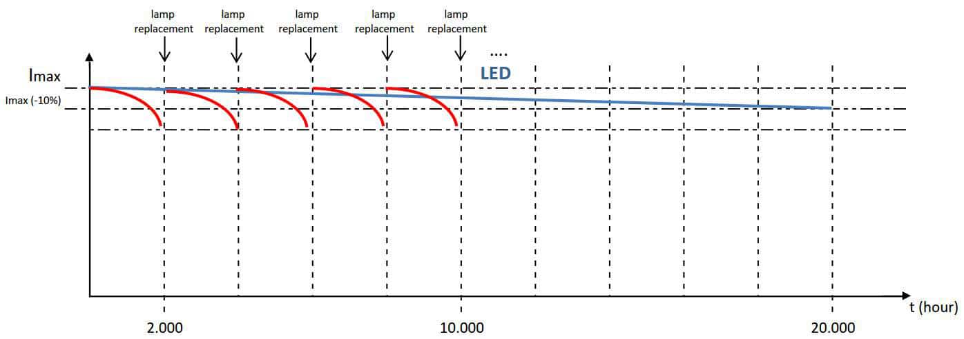
The main advantages of UV LED technology, comparing with UV lamps, are:

 Italiano
 Deutsch