Introduction
The remote control is an external device lets to control an UV QBe electronic power supply without using a PLC, using the controls provided by the device itself. The purpose of this document is to describe the operation and procedures for using it.
Main benefits
- Easy to use: once set just follow the ignition and shutdown sequences in the operating manual of the power supply and use the switches to control the operation of the power supply UV QBe; also with the LED indicators and the integrated display, you can know at any time at which power is running the power supply (implicitly, by reading the voltage of the signal AnlReq) and which are the feedback signals that the UV QBe power supply returns, including alarms.
- Cheap: its cost is relatively low compared to a low-end PLCs of the major brands, so making it ideal for use in those areas that are simple and mostly manual where the complexity of a PLC is not justifiable.
- Alternative to the PLC: where the programming logic is simple and can also be performed by the operator of the plant, using a PLC is wasteful both in terms of cost, of programming time and of resources dedicated, which are not always available in company.
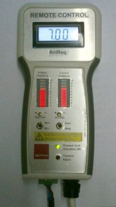
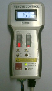
Device layout description (see the side image)
- Display: displays the value of the reference voltage of the analog signal (AnlReq)
- Voltage feedback: using a LED bar shows the value of the lamp voltage feedback (0-10V)
- Current feedback: using a LED bar shows the value of the lamp current feedback (0-10V)
- Max Ref: trimmer that allows the adjustment of the maximum value of the analog reference signal (AnlReq)
- Min Ref: trimmer that allows the adjustment of the minimum value (stand by) of the analog reference signal (AnlReq)
- Min-Max Switch: allows you to select the operation mode of the power supply, full power or stand-by
- Start-Stop switch: allow to switch on or off the lamp
- Allarms: red LED indicates overtemperature alarm, the green LED indicates the status of the ground fault (OK if it’s on)
- Terminal block: +24 V DC
Parameters setting
The parameters that you can adjust, displaying the value on the display are:
- Max Ref: maximum value of the analog reference (default value 7V)
- Min Ref: minimum value (stand-by) analog reference (default value 1.5 V)
The setting mode is the same for both parameters, described as follows:
- Make sure the remote control is supplied with the connector 9 (+24 V)
- Set the selector Min-Max (6) to the value you want to adjust
- By rotating the corresponding trimmer (4 or 5) adjust the desired voltage value
These values can also be modified with power UV QBe running.
WARNING! IN CASE OF EMERGENCY STOP, YOU MUST RESTORE THE SWITCH AT THE RIGHT TO THE ‘STOP’ POSITION TO PREVENT ACCIDENTAL RESTART OF THE UV QBE POWER SUPPLY WHEN THE EMERGENCY BUTTON WILL BE RESTORED
Alarms
The device is capable of displaying two types of alarm through the switching on or off of two LEDs :
- Overtemperature alarm: this alarm is connected to a red LED , which is activated if one of the temperature sensors into the UV QBe indicates the preset temperature threshold is exceeded, and this is generally a sign of a malfunction of the power modules. The activation of this alarm automatically turn off the power supply and a following restart of the UV QBe unit.
- Ground Fault Alarm : this alarm is connected to a green LED , which is normally on when the power supply is protected against output leakage currents to earth, in this case the green LED on the remote control will turn off . Turning off this LED does not automatically turn off the power supply.
![[:it] Silap[:en]Silap[:de]Silap[:]](https://www.silap.com/wp-content/uploads/2015/06/testats-spm.jpg)
![[:it] Silap[:en]Silap[:de]Silap[:]](https://www.silap.com/wp-content/uploads/2015/07/remote_control_news-2.jpg)

 Italiano
 Deutsch